My previous post describes my new venture into RFID hacking using a Tastic RFID stealer. The Tastic gadget requires a serial 4×20 LCD to display a proximity cards site code and serial number. I purchased a ByVac BV4618 LCD as a replacement to the LCD listed in the Tastic specifications due to local availability.

As Sopwith always advises, the first thing you need to do with a new gadget is to download the datasheet. You can find it here. The internal controller/driver of the LCD is a Hitachi HD44780. This very popular device can be found in all types of LCD applications. The BV4618 piggybacks on the HD44780 providing a very convenient communication interface.
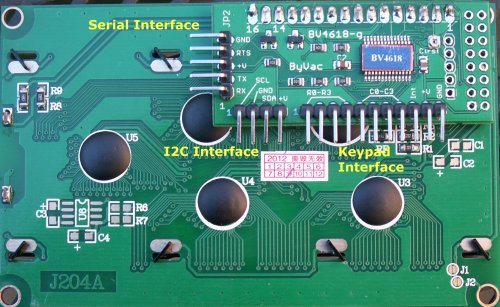
The BV4618 provides three interfaces. A serial interface provides support for both TTL and RS-232. This means you can connect a MCU such an Arduino or Raspberry PI, or use 12V serial connections to a serial port on a PC. There is also an I2C interface and support for a small numeric keypad.
Let’s see if we can get this cool little gadget up and running without producing any smoke. Wiring an Arduino Uno to the LCD is a snap. You can see a wiring diagram here. You can see in the diagram, power is provided to the LCD from the Arduino 5+ and ground pins. Pin-0 (Rx) from the Arduino is wired to the Rx pin on the BV4618. Pin-1 (Tx) goes to the BV4618 Tx pin. Done. Nothing could be simpler.
No wait! It can be simpler. If you do not need to ‘read’ anything from the LCD such as the firmware version, device ID, or ACK’s after sending a command, you can discard the Arduino Pin-0 (Rx) connection. Now what we have is a working LCD requiring only three wires – power, ground, and a Tx. This is why the designers of the Tastic RFID stealer used a serial I/F LCD. It simplified the design.
Now that the LCD is wired up, power up your Arduino and you should see the LCD come to life. The device is ‘smart’ enough to figure out you want to talk to it though the TTL serial I/F. The BV4618 is also smart enough to automatically configure the baud rate. It does this by looking for a CR byte (0x13) when powered up. That is why you see a ‘Press CR’ on the display.
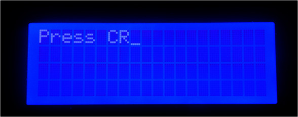
LCD waiting CR initiator
In Part-2 of this series I will show how to install the required Arduino libraries for the BV4618 LCD. Then we can cut some code!
Sopwith