Have not blogged much over the summer because the Mrs. and I have moved to London on a temporary work assignment. Anyone who has been an expat understands the complexities of a relocation. Now that we are here and settled, I can get back to my hacking projects. I bought my Rasberry Pi’s with me and purchased a couple of Arduino’s and bench tools at a local Maplin store.
My latest interest is in RFID cards. The use of this technology is exploding. Since I am in the security business, understanding how RFID is used for secure access to large data centers and other secure facilities is important. In my research, I came across an interesting project involving an Arduino Nano. The Tastic RFID stealer is a very clever hack.
This project involves the hack of a HID long-range proximity reader. Trust me, O’l Sopwith is not interested in stealing and cloning other peoples access cards. I am only interested in understanding the technology and seeing the bits fly across the air gap.
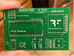
My first task was to get my hands on a Tastic circuit board and order the required parts. The Tastic web site of BishopFox does not sell the circuit boards, but does provide all the Gerber files containing details of the board layout. I took these files and uploaded them to OSH Park. This is an outfit that collects large numbers of small PCB fabrication orders and submits them for production at a fab plant during non-peak hours. Brilliant idea and great prices too. I ordered three Tastic PCB’s for about $25 USD.
Using the Tastic provided required parts list, I began collecting all the pieces needed to build the board. In a foreign land, this turned out to be harder than I thought. There are electronic stores here, but Radio Shack’s are rare. Ordering parts from the US is not practical due to the high cost of shipping. Also, anything purchased outside the EU is taxed at 20%. Farnell/element14 is based here and there service is fantastic.
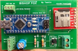
I soldered all the parts to one of the PCB’s and tested the Arduino Nano. Works great.
The only thing I could not find was the specific 20×14 LCD listed in the parts list. It is available at Amazon in the US, but I could not find it anywhere over here. I am required to use a serial I/F because the circuit board is wired for it. I am sure the Tastic designers chose a serial I/F because you can get away with using three wires (V+, Gnd, Tx). You do not need an Rx line because you only need to write to the LCD, not read from it.
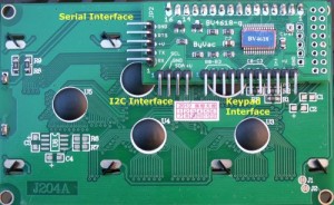
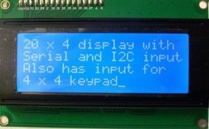
After a lot of searching, I came across an interesting LCD made by ByVac here in England.
This LCD has both a serial (TTL & RS-232) and I2C interfaces. I would have preferred to use the I2C I/F, but I have to stick to the design requirements. The really interesting thing about this board is that the controller uses VT100 tty commands to talk to the LCD. It also has an I/F for a small keypad, something of no interest to me in this project.
More details about this board in the next post.
Sopwith


Awesome great response time also if you don’t mind can you send me the exact files you sent to them just having trouble trying to send it on the format they want they want you to upload them now on there if it’s not to much to ask for I would highly appreciate it
Were did you get that Tastic RFID Stealer PCB from
Hi Adonis,
As stated in my blog post, you have to download the circuit board Gerber files from the BishopFox website. Next, you need to upload those files to a PCB manufacturer. The outfit I used is OSH Park. The boards are very inexpensive. I recommend you order a couple of them in case you make a mistake when soldering on the components.
Sopwith