In Part-1 of the Prusa i3 MKS3S 3D printer kit build, I gave a brief overview of my build experience. In Part-2, I provided more details of putting the printer together. Here in Part-3, I finish up describing the challenges I had during the assembly process.
NOTE: Remember, the below steps are just highlights of my assembly experience. They do not match the assembly steps in the manual.
Step-7 – Installing the X and Y belts. As the build continued, the number of parts to physically work around as you assemble components increases. I found the section on belt installation challenging. The toothed belts are provided flat – not a continuous loop. You have to bend a belt end tightly around a bolt on the belt tensioners, and run them around pulleys.
Impression-7 – This part of the assembly took way longer than it should. It was very difficult to determine how to set the correct tension. This caused me great pain later in the assembly. I would say the belts mechanisms are one of the most important parts of a 3D printer.
Step-8 – Assembling the PSU. You may recall in Step-5, I assembled the PSU mounting bolts on the wrong side of the rail. Now that the printer was 75% assembled, it came to haunt me. When I went to mount the PSU, the screws were on the wrong side.
Impression-8 – The manual was very predictive. “Incorrect placement of the PSU holders will lead to issues later,” is the ground truth. I had to disassemble a lot of parts to correct this issue.
Step-9 – Electronics assembly is a slow process. Section 8 of the manual focuses on the printer electronics. It is a major understatement when I say there are a lot of wires and they go to a lot of places. And, there is not a lot of room to work in the “control box” area.
Impression-9 – Take your time with the wiring to make sure you get it right.
Step-10 – Diverting disaster. In step 24 of the manual, there are important instructions on wiring up the PSU to the motherboard. Apparently, there are two different versions of the cable sets, Version-A and Version-B. Version-A wires are black and the positive wire is marked with a RED line. Version-B there is a red and black wire, and the positive wire is solid red.
Well, I must have gotten Version-C, because my wires matched neither description. They were colored differently than the photos. Now I was stuck. And I surely did not want to reverse polarity from the power supply to the motherboard!. I wired up the PSU to the motherboard by using an ohm meter and ensuring the polarity was correct between the two components.
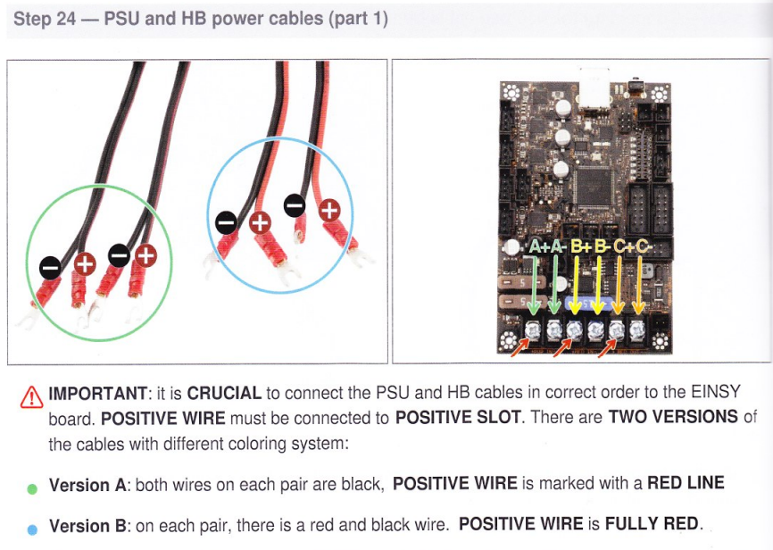 The wires in my kit did not match either of these color schemes.
Impression-10 – This issue problem could be really problematic for less experienced Makers. Prusa must ensure the wiring colors match the assembly manual. Why they cannot standardize on a single PSU wire specification is puzzling to me.
Step-11 – The wires don’t fit. Once I got most of the wiring sorted, it was time to button up the control box. In step 30, the task is to run the extruder cable bundle through the extruder-cable-clip and secure the clamp with a couple of screws. This is all shown neatly in the below page copy.

My problem was, the cable bundle is a whole lot thicker than the one in the photo. It took me forever to get the clamp secured around the huge bundle of wires. I refused to give up on it until I somehow got it done.
I know I am not the only one to experience this. How do I know? Because I have watched a lot of YouTube videos of Makers using their printers. When I look closer to their printer control boxes, I can see all kinds of messes. Some guys just used black tape and called it a day. Others just left the wires hanging out.
Impression-11 – This is another design problem that needs to be fixed. It may be time to consider splitting the wire bundle and using two entry points into the cage for the wire set.
Once I got the wiring done, I completed the assembly of the printer and went on to firing it help. I describe this exciting moment in Part-4.